Site Plans
A site plan shows the entire block of land, or at least the part of the block where the building will be.
Site plans are drawn at a small scale so that they can show the entire block of land (or at least the part of the block where the building will be). Most importantly, they show where the building is to be located on the block.
Site plans also typically show things like driveways, fences, clothes lines, paths and retaining walls. These things are called ‘ancillary’ works (that is, additional to the main building works and usually of a relatively minor nature). In some cases, the ancillary works are not included in the building contract; the owner organises them later.
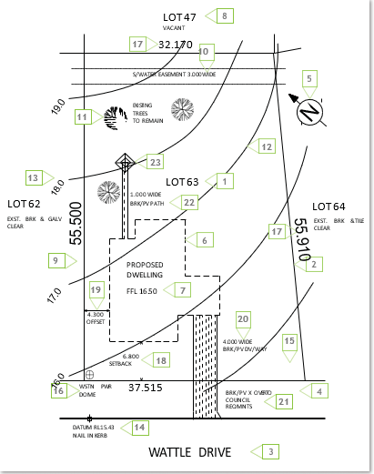
Figure 1.2 is a site plan for a residential project. You’ll see that lots of parts of it are numbered. A description of these numbered features is provided after the plan. Find each numbered feature on the site plan, then read the information about it.

- Block identification. When land is subdivided, each block is given a lot number. The street number is allocated later.
- Boundary. The boundary is the imaginary line that defines the block of land. At each corner is a small wooden peg with the numbers of the adjacent lots stamped onto a metal plate. If a boundary changes direction, a peg is located at that point too.
- Road identification. The name of the road shows where the front of the block is.
- Verge. The verge is the area of land between the block and the road. It is not part of the block and must not be built on (apart from a crossover) or damaged in any way. It usually has services running beneath it (water, telephone, etc).
- North point. The direction of north is shown to assist in orientating the drawing with the block when on-site.
- Proposed building. The location of the proposed house is shown, usually just as an outline.
- Finished floor level. The level of the finished floor of the house is given.
- Adjacent properties. The adjacent lot numbers are shown, and sometimes indications of existing structures are given.
- Existing fences. Any existing boundary fences should be shown.
- Easement. An easement is a part of the land over which another party has some sort of legal right. In this case, a strip near the rear of the block is an easement for a council stormwater line to be laid. It still belongs to the landowner but the council has the right to lay and maintain a stormwater pipe there, so no structure is allowed to be built over this area.
- Existing trees. If there are any features on the block that are to be left undisturbed they are clearly indicated.
- Contour lines. These are imaginary level lines that indicate the shape of the land (you might have seen these on maps). In this site plan, they indicate that the land slopes down from the north corner to the south corner.
- Contour level. This indicates the ‘reduced level’ of the contour (reduced levels are explained in Section 3 Dimensions of this guide). In this case, they are shown at one-metre intervals, but this varies depending on the steepness of the land.
- Datum. This is a point on or near the block that all heights for the project are measured from. It is explained more fully in Section 3.
- Angle of boundary intersection. This indicates at what angle the boundaries meet. It is not always shown, especially if the block has square corners.
- Location of power connection. This indicates to the electrician where the electrical connection will be made. In this case, the block has underground power, but if overhead lines pass the block, the nearest power pole may be shown.
- Boundary length. This indicates the length of each boundary.
- Setback. This is the distance from the front boundary to the nearest part of the building. A minimum distance for this is set by the local authority (council) and varies depending on the zoning of the land.
- Offset. Similar to the setback, the offset indicates how far from the side boundary the building is to be. There are by-laws regulating the minimum distance for this, mainly to minimise the spread of fire.
- Driveway. This indicates where and how wide the driveway should be.
- Crossover. This is the continuation of the driveway across the verge.
- Path. Any paving included in the contract is shown.
- Clothes hoist. The position of the clothes hoist is indicated.
